Introduction: Navigating Precision and Reliability in Custom Mold Tooling
In modern high-pressure die casting (HPDC) and precision injection molding operations across automotive manufacturing, aerospace components, industrial machinery, telecommunications infrastructure, medical device enclosures, and high-end consumer electronics, off-the-shelf standard mold parts frequently fail to satisfy demanding engineering requirements. Complex casting features, aggressive thermal conditions, ultra-tight dimensional tolerances, and specialized alloy chemistries mandate the procurement of custom die casting mold parts tailored specifically to unique tooling geometries.
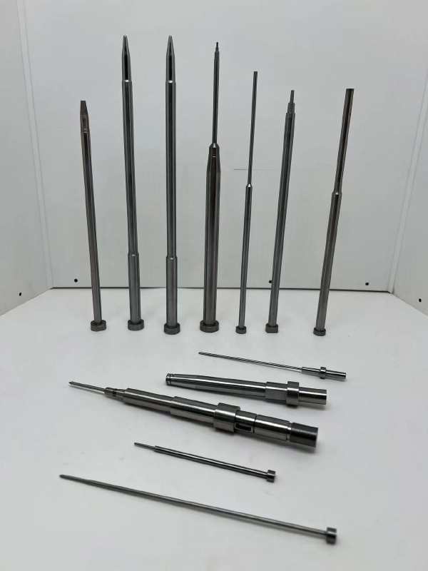
Sourcing non-standard core pins, cavity inserts, slider blocks, guide bushings, wear plates, nozzle inserts, and internal cooling components requires navigating technical details across steel metallurgy, multi-axis precision machining, vacuum heat treatment validation, surface engineering, and quality control protocol. A single error in drawing interpretation, steel grade selection, tolerance callout, or post-processing heat treatment can lead to costly mold downtime, premature tool degradation, elevated scrap rates, and severe production bottlenecks.
This comprehensive technical procurement guide covers every critical aspect of sourcing custom die casting mold parts, including tolerance specifications, tool steel matching, manufacturing process validation, advanced surface engineering, cost breakdown structures, supplier auditing, and lead time optimization.
1. Technical Drawing Requirements and Key Tolerance Parameters
Complete, fully defined technical documentation is the foundation of precision mold component manufacturing. Sourcing success depends on delivering precise 2D GD&T (Geometric Dimensioning and Tolerancing) drawings alongside clean 3D CAD models (STEP/IGES formats) to your manufacturing partner.
Essential Specifications for Custom Mold Part Technical Drawings
- Critical Fitting Dimensions & Interlocking Fits: Explicitly highlight tight micro-scale tolerances for fitting diameters, core pin shanks, insert pocket steps, and locator alignments.
- Geometric Dimensioning and Tolerancing (GD&T): Call out explicit geometric controls, including concentricity, cylindrical tolerance, perpendicularity, parallelism, and surface runout relative to specified datum planes.
- Surface Finish Specifications (Ra / Micro-inch): Define Ra roughness values based on functional requirements (e.g., sliding guide faces Ra 0.2–0.4 µm, pocket seating faces Ra 0.4–0.8 µm, cavity molding surfaces Ra 0.05–0.1 µm / SPI A1 mirror polish).
- Material Grade and Heat Treatment Callouts: Specify exact tool steel standard grades (e.g., AISI H13 ESR, DIN 1.2344 ESR, DIN 1.2367 ESR) and required core and surface hardness values in Rockwell C (HRC) or Vickers (HV).
Machining Tolerances for Custom Die Casting Mold Components
| Component Category | Key Features & Geometries | Standard Custom Tolerance Range | High-Precision Tolerance Range |
|---|---|---|---|
| Core Pins & Ejector Pins | Shank Outer Diameter (OD), Step Steps, Positioning Head | ±0.005 mm to ±0.010 mm | ±0.002 mm to ±0.005 mm |
| Cavity & Core Inserts | Pocket Seating Fit Dimensions, Height Steps, Mating Locks | ±0.010 mm to ±0.020 mm | ±0.003 mm to ±0.008 mm |
| Guide Pins & Bushings | Mating Diameters, Concentricity, Total Surface Runout | ±0.003 mm to ±0.008 mm | ±0.001 mm to ±0.003 mm |
| Slider Blocks & Wear Plates | Flatness, Parallelism, Sliding Guide Fit Widths | ±0.010 mm to ±0.015 mm | ±0.005 mm to ±0.008 mm |
| Cooling Inserts & Manifolds | Internal Channel Alignment, O-Ring Seating Grooves, Threads | ±0.020 mm to ±0.050 mm | ±0.010 mm to ±0.020 mm |
2. Selecting the Right Tool Steel for Custom Die Casting Mold Parts
Selecting appropriate steel grades for custom die casting components requires balancing hot hardness, thermal fatigue resistance, impact toughness, wear resistance, and thermal conductivity based on the cast alloy (Aluminum, Zinc, or Magnesium).
Key Tool Steel Grades for Die Casting Applications
| Steel Grade Standard | Equivalent International Standards | Key Mechanical Characteristics | Primary Component Applications |
|---|---|---|---|
| Standard H13 | AISI H13 / DIN 1.2344 / JIS SKD61 | Balanced toughness, moderate hot hardness, reliable machinability. | Standard ejector pin plates, support pillars, core holder blocks, backing plates. |
| H13 Premium (ESR) | AISI H13 ESR / DIN 1.2344 ESR / SKD61 ESR | High isotropic purity, refined grain structure, superior resistance to thermal fatigue. | High-stress cavity inserts, custom core pins, runner blocks, main die cores. |
| DIN 1.2367 ESR | DIN 1.2367 ESR / X38CrMoV5-3 ESR | High Chromium (5%) and Molybdenum (2.8%) content, exceptional hot strength and temper resistance. | High-temperature aluminum casting inserts, gating core pins, heavy thermal load inserts. |
| Dievar / Unimax Class | Proprietary High-Performance Tool Steels | Superior ductility, maximum crack propagation resistance, extended thermal fatigue life. | Large structural automotive aluminum castings, high-volume cores, complex thin-wall inserts. |
| AISI S7 / DIN 1.2767 | AISI S7 / DIN 1.2767 / 45NiCrMo16 | High impact toughness, excellent shock load resistance, lower thermal capability. | Zinc die casting inserts, heavy-impact slider mechanisms, mechanical wedge locks. |
Steel Selection Guidelines by Cast Alloy
- Aluminum Die Casting (Casting Temp: 650°C – 700°C): Requires high thermal fatigue resistance. Premium ESR steels (H13 ESR, 1.2344 ESR, 1.2367 ESR, or Dievar) hardened to 46–52 HRC are mandatory for cavity-contact components.
- Zinc Die Casting (Casting Temp: 400°C – 430°C): Lower thermal shock allows higher working hardness (48–54 HRC) focused on wear resistance and surface polishability. Standard H13, S7, or pre-hardened tool steels deliver reliable performance.
- Magnesium Die Casting (Casting Temp: 620°C – 680°C): Highly reactive with rapid cooling rates. Demands high-toughness steels (H13 ESR, 1.2344 ESR) combined with specialized anti-soldering surface coatings.
3. Advanced Manufacturing Processes for Custom Mold Parts
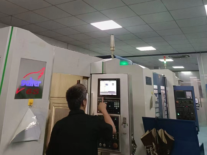
Achieving sub-micron precision and reliable surface integrity on custom mold parts requires multi-axis CNC machining, high-precision grinding, and electrical discharge machining (EDM).
Primary Manufacturing Operations
- 5-Axis High-Speed CNC Milling: Enables single-setup machining of complex 3D contoured cavity inserts, runner systems, and cooling manifolds, preserving geometric alignment and position accuracy.
- CNC Turning & Swiss Machining: Ideal for rotational parts such as custom core pins, ejector pins, guide sleeves, and cooling nipples requiring tight coaxiality and runout control.
- Wire EDM & Sinker EDM: Essential for sharp internal corners, narrow slots, non-circular features, and complex internal ribs. High-precision wire EDM produces sub-micron micro-finishes that minimize post-polish labor.
- Cylindrical & Surface Grinding: Delivers high accuracy (±0.001 mm) and smooth finishes on guide pins, positioning locator steps, core pin shanks, and slider sliding faces.
Post-Processing and Surface Modifications
To extend mold part operating life, advanced surface modifications are applied following vacuum heat treatment and finish machining:
- Plasma Nitriding (Ion Nitriding): Diffuses nitrogen into steel surfaces, producing a wear-resistant diffusion case (50–120 µm depth, 65–70 HRC equivalent) without dimensional distortion.
- PVD Ceramic Coatings (AlTiN, CrN, TiAlN): Thin ceramic films (2–4 µm) that act as thermal barriers and reduce friction coefficients, preventing aluminum soldering and galling during high-pressure metal injection.
- Precision Mirror Polishing: Manual, mechanical, and ultrasonic polishing up to SPI A1 / Ra 0.02 µm for optimal part release and superior aesthetic casting quality.
4. Supplier Evaluation and Quality Assurance Verification
Partnering with a reliable mold component manufacturer requires evaluating their production equipment, thermal processing controls, and quality inspection infrastructure.
Essential Supplier Audit Checklist
- In-House Heat Treatment Controls: Ensure the supplier operates calibrated vacuum furnaces with documented multi-stage preheating, high-pressure gas quenching, and triple tempering records.
- Quality Inspection Laboratory Capabilities: Verify access to climate-controlled metrology rooms equipped with Coordinate Measuring Machines (CMM), optical measuring systems, laser micrometers, surface roughness testers, and hardness testers.
- Raw Material Traceability: Require official Mill Test Certificates (MTC EN 10204 3.1) for every batch, confirming steel chemistry, ESR refining certification, and ultrasonic flaw detection compliance.
Recommended Quality Assurance Process Flow
| Inspection Stage | Key Inspection Parameters | Quality Verification Documentation |
|---|---|---|
| Incoming Material Verification | Steel chemical composition, ultrasonic internal crack check, raw hardness | Mill Test Certificate (MTC / EN 10204 3.1) |
| In-Process Machining Audit | Semi-finished dimensions, EDM recast removal, rough grind allowances | First-Article Inspection Report (FAIR) |
| Heat Treatment Validation | Core and surface hardness testing (HRC/HV), microstructural evaluation | Heat Treatment Log & Hardness Test Certificate |
| Final Precision Metrology | 100% GD&T validation, micro-tolerances, surface roughness (Ra) check | 100% Final CMM Dimensional Metrology Report |
5. Cost Drivers, RFQ Preparation, and Lead Time Optimization
Detailed Cost Breakdown Structure for Custom Mold Components
Understanding where costs originate during the custom component manufacturing cycle enables procurement teams to negotiate effectively, identify optimization opportunities, and avoid unnecessary tooling expenses without sacrificing performance.
| Cost Category | Percentage of Total Unit Cost | Primary Cost Drivers | Cost Reduction Optimization Strategy |
|---|---|---|---|
| Specialty Raw Tool Steel | 20% – 35% | Steel cleanliness grade (Standard vs. ESR/VAR), exotic chemistries (Dievar, 1.2367 ESR), heavy shank stock sizes. | Standardize stock diameters across tooling series; order raw steel in batch pre-cut lengths. |
| Multi-Axis Precision Machining | 35% – 50% | 5-axis CNC programming hours, tight tolerances requiring slow grinding speeds, deep wire/sinker EDM burn times. | Avoid unnecessarily tight tolerances on non-molding support surfaces; simplify internal cooling channel radii. |
| Vacuum Heat Treatment & Stress Relief | 10% – 15% | Multi-stage vacuum furnace cycles, triple tempering requirements, cryogenic treatments, post-EDM stress relief. | Group custom components into larger thermal batch lots to share vacuum furnace fixed cycle costs. |
| Surface Modifications & Coatings | 8% – 15% | Duplex plasma nitriding, specialized PVD ceramic coatings (AlTiN, CrN), multi-stage precision mirror polishing. | Apply specialized PVD coatings only to high-wear molding faces rather than non-functional mounting surfaces. |
| Metrology & CMM Quality Auditing | 5% – 10% | 100% full GD&T CMM inspection, surface roughness profilometry, optical comparator verification, MTC certification. | Define critical vs. non-critical dimensional inspection plans for recurring batch runs. |
Primary Cost Drivers in Custom Mold Component Sourcing
- Material Grade Cleanliness: Specifying premium ESR/VAR tool steels increases raw material costs by 40–80% over standard commercial grades, but yields substantial gains in tool longevity and reduced downtime.
- Tightness of Tolerances: Specifying micro-scale tolerances (±0.002 mm vs. ±0.010 mm) requires additional precision grinding steps and slower EDM burning speeds, increasing unit machining costs.
- Specialized Surface Modifications: Adding plasma nitriding or PVD coatings adds batch processing operations, but drastically cuts costs associated with downtime caused by solder buildup.
- Order Volume and Batch Size: Low-volume custom orders (1–5 pieces) carry higher fixed setup costs per unit compared to larger batch runs (20–100 pieces).
How to Prepare a Rapid-Response RFQ Packet
To receive accurate technical quotes within 24–48 hours, ensure your RFQ package includes:
- Complete 2D engineering drawings (PDF format with clear GD&T callouts) and 3D CAD files (STEP/IGES format).
- Exact tool steel specifications and required working hardness range (HRC).
- Surface modification specifications (e.g., nitriding case depth, PVD coating type, polish level).
- Required delivery quantities (initial prototype/sample count versus recurring annual batch sizes).
- Packaging, rust protection, and target delivery timelines.
Typical Production Lead Times and Fast-Track Strategies
- Standard Custom Turned/Ground Components (Core Pins, Bushings): 7 to 12 business days.
- Complex Cavity Inserts (5-Axis Milling + EDM + PVD Coating): 15 to 25 business days.
- Fast-Track Inventory Strategy: Maintain pre-rough-machined core pin blanks in standard shank sizes, allowing rapid finish-turning, wire EDMing, and surface treatment when urgent replacement parts are required.
Frequently Asked Questions (FAQ)
Q1: What are the key details required to receive an accurate quote for custom die casting mold parts?
An accurate RFQ packet should include 2D drawings with GD&T tolerances, 3D CAD models in STEP format, tool steel grade specifications (e.g., H13 ESR or 1.2344 ESR), target core and surface hardness (HRC), required surface treatments (e.g., nitriding, PVD coating), and order quantities.
Q2: Why is ESR (Electro-Slag Remelted) steel strongly recommended for custom core pins and inserts?
ESR steel undergoes continuous remelting through a reactive slag layer, removing non-metallic inclusions and creating uniform isotropic properties. This results in significantly higher transverse impact toughness, superior thermal fatigue resistance, and extended service life under cyclic thermal shock compared to standard air-melted tool steel.
Q3: What is the average lead time for custom non-standard mold components?
Lead times for custom mold parts typically range from 7 to 12 business days for rotational ground parts (such as core pins and bushings) and 15 to 25 business days for complex 5-axis milled inserts requiring heat treatment, EDMing, and PVD coating. Fast-track options are often available for critical tool repairs.
Q4: How can I prevent distortion in custom mold components during heat treatment?
To prevent thermal distortion, specify vacuum hardening with multi-stage preheating and high-pressure gas quenching. Always leave adequate grinding stock (0.15–0.30 mm) on semi-finished components to allow final precision grinding after heat treatment.
Q5: What surface treatment best prevents molten aluminum soldering on core pins and cavity inserts?
A duplex coating system combining plasma nitriding with a Physical Vapor Deposition (PVD) ceramic film (such as AlTiN or CrN) provides optimal protection against aluminum soldering. The coating forms a chemically inert thermal barrier that prevents direct metallic bonding between molten aluminum and iron in the tool steel.