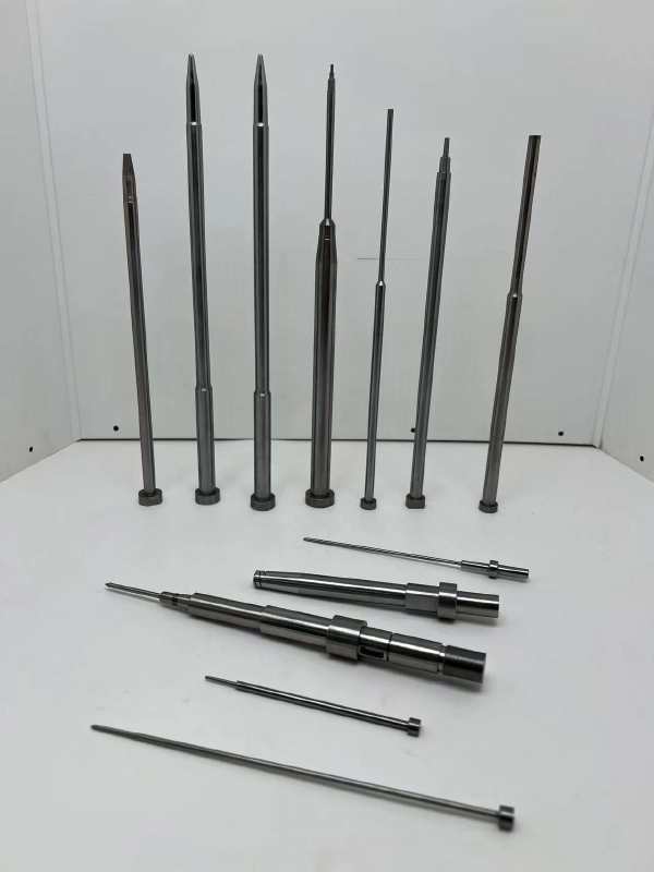
Introduction: The Costly Challenge of Core Pin Failure in High-Pressure Die Casting
High-Pressure Die Casting (HPDC) demands exceptionally rigorous performance from mold components and tooling elements. Among all high-stress mold parts, custom die casting core pins operate under some of the most unforgiving thermal, mechanical, and tribological environments in modern industrial manufacturing. Frequently exposed to cyclic operating temperatures ranging from over 680°C during molten aluminum injection down to ambient or cooling fluid temperatures within milliseconds, core pins are subjected to continuous thermal shock, cyclic high-frequency stress, intense hydrodynamic erosion, and severe chemical interactions with reactive molten alloys.
When custom core pins suffer from premature thermal fatigue—commonly referred to as heat checking—or undergo catastrophic bending and breakage, die casting foundries and component manufacturers face severe operational and financial consequences. These failures result in unscheduled machine downtime, elevated casting scrap rates, damaged mold cavities, expensive tool room repairs, and missed production deadlines. To optimize tool maintenance budgets, maximize overall equipment effectiveness (OEE), and maintain structural casting integrity, tooling engineers and foundry operations managers must implement a comprehensive, science-based approach to core pin reliability.
This technical engineering guide explores the root failure mechanisms affecting custom core pins across aluminum, zinc, and magnesium die casting operations. It provides actionable engineering solutions spanning raw tool steel selection, advanced vacuum heat treatment protocols, post-EDM stress relief treatments, duplex surface engineering, conformal cooling architectures, and precision manufacturing tolerances.
Understanding Core Pin Failure Modes: Thermal Fatigue vs. Mechanical Breakage
To systematically diagnose and eliminate core pin failure, tooling designers and quality managers must first understand the fundamental physical and metallurgical mechanisms occurring inside the high-pressure mold cavity during the casting cycle.
1. Thermal Fatigue (Heat Checking)
Thermal fatigue, or heat checking, manifests as a dense network of micro-cracks across the functional surfaces of core pins. It is driven by steep, localized thermal gradients between the outer surface skin of the core pin and its internal core during rapid thermal cycling.
During the cavity filling stage, high-temperature molten metal floods the mold, rapidly heating the outer skin of the core pin while the cooler inner core restrains thermal expansion. This differential expansion generates high compressive stresses at the pin surface. When the casting solidifies and is ejected, followed by automated die lubricant spraying, the pin surface undergoes rapid chilling. The outer skin contracts rapidly against the hot core, flipping the local stress state into severe tension. Over thousands of production cycles, these repetitive compressive-tensile stress oscillations exceed the yield strength of the steel, initiating surface micro-cracks that progressively propagate deeper into the core pin substrate. Thermal fatigue degrades cast surface finish, leads to flash formation, and promotes mechanical interlocking with the casting.
2. Mechanical Bending, Distortion, and Catastrophic Breakage
Unlike thermal fatigue, which develops progressively over extended production runs, mechanical bending or sudden pin breakage can occur abruptly during early casting cycles or propagate rapidly from existing thermal micro-cracks. Key contributing factors include:
- High Injection Hydrodynamic Pressure: Extreme molten alloy flow velocities (often exceeding 40–50 m/s at the gate) exert powerful lateral bending forces on slim, unsupported, or long-reach core pins.
- Thermal Shock and Tensile Overload: Unrelieved residual internal stresses from aggressive machining or improper heat treatment combine with external bending loads, exceeding the ultimate tensile strength of the hardened tool steel.
- Ejection Misalignment and Friction Drag: Non-uniform cooling or solidification shrinkage causes cast metal to grip tightly around the core pin body. During mechanical part ejection, high drag forces generate bending moments that snap unyielding core pins.
3. Molten Metal Erosion and Soldering (Galling)
In aluminum die casting, chemical affinity between molten aluminum and iron-based tool steel triggers chemical dissolution and intermetallic phase reaction (soldering). Molten aluminum reacts with the core pin surface to form brittle Fe-Al intermetallic compounds (e.g., Fe3Al, FeAl3). As aluminum adheres to the core pin, part stripping forces increase dramatically, creating severe friction that frequently leads to pin bending, mechanical galling, or complete pin fracture during stripping.
Root Cause Analysis: Why Do Custom Core Pins Fail Prematurely?
Diagnosing core pin failures requires analyzing four primary variables: material purity, heat treatment execution, cooling efficiency, and geometric design features.
| Failure Mode | Primary Root Cause | Contributing Manufacturing/Operational Factors | Recommended Engineering Solution |
|---|---|---|---|
| Early Heat Checking | Low thermal fatigue resistance / Low temper resistance | Using standard commercial H13 steel without premium electro-slag remelting (ESR) or proper triple tempering. | Upgrade to premium ESR hot-work steels (e.g., Dievar, 1.2344 ESR, 1.2367 ESR) with deep triple tempering. |
| Catastrophic Snap / Breakage | High notch sensitivity, insufficient core toughness, or excessive working hardness | Over-hardening above 52 HRC, aggressive wire EDM without stress relief, sharp step transition radii (<0.3mm). | Maintain core toughness (46–50 HRC target), perform post-EDM sub-critical stress relief, add generous fillets (>0.5mm). |
| Soldering and Metal Galling | Direct metal-to-metal chemical diffusion between molten alloy and tool steel | Uncoated core pin surface, improper die lube spray coverage, localized thermal hot spots exceeding 450°C. | Apply PVD coatings (AlTiN, CrN) or plasma nitriding duplex layers; integrate high-pressure internal jet cooling. |
| Pin Bending / Dimensional Distortion | High length-to-diameter ratio (L/D > 5:1) paired with direct gate impingement | Unsupported slender pin design positioned directly in front of high-velocity runner gate channels. | Relocate runner gate channels to avoid direct pin impingement; increase shank diameter or introduce step-shoulder support. |
Strategy 1: Select High-Performance Hot-Work Tool Steels
Selecting appropriate steel chemistry, melt cleanliness, and refining method is the foundational requirement for long-lasting custom core pins. Commodity tool steels contain micro-segregation, non-metallic inclusions, and anisotropic grain structures that accelerate crack initiation and propagation.
Standard Commercial H13 (1.2344) vs. Electro-Slag Remelted (ESR) Steels
Standard air-melted H13 tool steel is acceptable for non-critical mold components, but high-stress custom core pins demand Electro-Slag Remelted (ESR) or Vacuum Arc Remelted (VAR) hot-work tool steels. The ESR refining process continuously remelts steel through a reactive slag layer, removing non-metallic inclusions (oxides and sulfides), refining grain structure, and producing uniform, isotropic mechanical properties in both longitudinal and transverse directions. ESR steels exhibit significantly higher transverse impact energy and ductility compared to standard air-melted grades.
Advanced Steel Grades Engineered for High-Stress Core Pins
- H13 Premium / DIN 1.2344 ESR / JIS SKD61 ESR: The industry standard for high-durability core pins. Offers excellent microstructural cleanliness, balanced impact toughness, and good thermal conductivity when properly heat-treated.
- DIN 1.2367 ESR (X38CrMoV5-3): Contains higher levels of chromium (~5.0%) and molybdenum (~2.8%) than standard H13. Features elevated hot hardness, superior tempering resistance up to 600°C, and exceptional resistance to heat checking under aggressive thermal loading.
- Dievar / Unimax Premium Specialty Steels: Proprietary hot-work tool steel chemistries engineered specifically for severe die casting environments. They feature exceptionally high ductility, crack growth resistance, and thermal fatigue life, far exceeding conventional standard H13 performance.
- Molybdenum & Tungsten Alloys (e.g., TZM, Anviloy): Refractory metal alloys utilized in extreme thermal density zones where tool steel pins repeatedly wash out or solder despite active cooling. Molybdenum alloys boast thermal conductivity up to three times higher than steel, low thermal expansion coefficients, and high immunity to aluminum soldering.
Strategy 2: Precision Heat Treatment and Stress Relief Protocols
Superior raw tool steel will fail prematurely if subjected to substandard heat treatment. Metallurgical processing dictates core pin toughness, hot strength, and dimensional stability.
1. Multi-Stage Vacuum Hardening with High-Pressure Gas Quenching
Custom core pins should undergo vacuum heat treatment featuring multi-stage preheating cycles (e.g., 650°C and 850°C) to equalize internal temperatures and minimize thermal distortion. High-pressure gas quenching using nitrogen ensures rapid cooling through the critical transformation zone, producing a fine, fully martensitic microstructure while preventing grain boundary carbide precipitation.
2. Mandatory Triple Tempering Protocol
Tempering converts fresh, brittle martensite into tempered martensite while breaking down retained austenite. To maximize toughness and set target operating hardness (typically 46–52 HRC depending on pin geometry and casting alloy), custom core pins must undergo at least three distinct temper cycles. The final tempering temperature must exceed the maximum localized operating temperature expected during die casting to prevent hardness loss during production.
3. Post-EDM Stress Relief Thermal Processing
Electrical Discharge Machining (EDM/Wire Cut) is essential for producing complex custom geometries on core pins. However, EDM leaves a brittle, highly stressed surface layer known as the “white layer” or recast layer. This layer contains micro-cracks and tensile stresses that act as immediate crack initiation sites under thermal cycling. Custom core pins must undergo micro-polishing to mechanically remove the recast layer, followed by sub-critical stress relief tempering at 20–30°C below the final tempering temperature.
Strategy 3: Advanced Surface Engineering and Duplex Coatings
Enhancing surface micro-hardness and chemical inertia without compromising core toughness extends core pin service life in demanding casting environments.
Plasma Nitriding (Ion Nitriding)
Plasma nitriding diffuses nitrogen into the pin surface, creating a hard diffusion layer (up to 900–1100 HV / ~65–70 HRC equivalent) and a thin compound layer. Nitriding drastically increases surface abrasion resistance and anti-soldering characteristics. However, nitrogen case depth must be controlled (typically 0.05–0.12 mm) to prevent surface embrittlement and spalling under heavy bending loads.
Duplex Surface Architecture (Nitriding + PVD Coating)
Combining plasma nitriding with Physical Vapor Deposition (PVD) produces a high-performance surface engineered for extreme die casting conditions:
- Chromium Nitride (CrN): Offers low friction against molten non-ferrous metals, strong chemical inertia, and high oxidation resistance up to 700°C.
- Aluminum Titanium Nitride (AlTiN / TiAlN): Features high hot hardness and high thermal oxidation resistance. Under high heat, AlTiN forms a protective micro-layer of aluminum oxide that prevents metal adhesion and oxidation.
- Synergistic Load Capacity: The hard underlying nitrided case supports the ultra-thin PVD ceramic film (2–4 µm), preventing plastic deformation of the soft steel substrate underneath (the “eggshell effect”) under high injection pressures.
Strategy 4: Optimized Internal Cooling Architecture and Geometry
Uncontrolled heat buildup accelerates thermal fatigue, lowers steel yield strength, and promotes aluminum adhesion. Effective thermal management keeps core pin temperatures within stable operating limits.
Conformal Cooling and High-Pressure Jet Cooling Systems
Integrating deep internal cooling channels—such as bubbler tubes, cascade baffles, or high-pressure jet cooling—directly inside custom core pins extracts heat from internal thermal hot spots. High-pressure jet cooling forces cooling water (10–20 bar) through inner tubes directly against the internal tip of slender core pins during part solidification. This rapid cooling cycle extracts core heat within seconds, suppressing peak thermal spikes and extending pin operating life by 200% to 400%.
Design Guidelines for High-Durability Custom Core Pins
- Generous Fillet Radii: All step transitions, shoulder changes, and internal cooling channel bottoms must feature generous fillet radii (R ≥ 0.5 mm – 1.2 mm) to minimize stress concentrations.
- Length-to-Diameter Ratio Control: Keep unsupported length-to-diameter (L/D) ratios below 5:1 wherever possible. For slim pins with higher L/D ratios, introduce step-up support shoulders or localized core support blocks.
- Longitudinal Surface Polishing: All molding and functional surfaces must be polished in the direction of part ejection to a mirror finish (Ra < 0.2 µm). Transverse grinding marks act as stress risers that accelerate heat checking and impede part release.
Comparison Matrix: Standard Commodity Pins vs. High-Durability Custom Core Pins
| Engineering Parameter | Standard Commercial Core Pins | Engineered High-Durability Custom Core Pins |
|---|---|---|
| Material Selection | Standard Commercial H13 (Air melted) | Premium ESR / VAR Steels (1.2344 ESR, 1.2367 ESR, Dievar) |
| Microstructural Cleanliness | Standard inclusion levels, anisotropic grain structure | Isotropic grain structure, ASTM E45 inclusion rating A,B,C,D < 0.5 |
| Heat Treatment Standard | Basic atmosphere furnace + double temper | Multi-stage Vacuum Hardening + Triple Tempering Cycles |
| Post-EDM Finishing | None or basic manual polishing | Recast layer removal + Sub-critical Stress Relief Tempering |
| Surface Modifications | Uncoated or simple black oxide finish | Plasma Nitriding / Duplex PVD Coating (AlTiN or CrN) |
| Cooling Architecture | Solid pin without cooling or simple straight hole | High-Pressure Jet Cooling / Conformal Bubbler Channels |
| Transition Step Fillets | Small radii or sharp corners (R < 0.2 mm) | Generous stress-relief transition fillets (R ≥ 0.5–1.2 mm) |
| Surface Roughness (Ra) | Ra 0.4–0.8 µm (Unpolished or turn-ground) | Ra 0.05–0.2 µm (Longitudinal mirror polishing) |
| Expected Service Life | 15,000 – 45,000 casting shots | 150,000 – 400,000+ casting shots (Depending on alloy & geometry) |
Key Engineering Takeaways for Tooling Designers and Foundries
- Specify ESR Steel Quality: Always mandate Electro-Slag Remelted (ESR) steel grades for core pins subjected to cyclic thermal shock and high injection pressures.
- Balance Toughness and Hardness: Maintain working hardness at 48–50 HRC for standard core pins, and adjust to 46–48 HRC for slim pins to maximize impact toughness and eliminate catastrophic snapping.
- Neutralize EDM Damage: Mechanically polish away the EDM recast layer and always perform a sub-critical stress relief temper prior to final surface coating.
- Implement High-Pressure Jet Cooling: Keep local pin core temperatures below 350°C during casting to prevent soldering and suppress thermal fatigue crack initiation.
- Apply Duplex Surface Treatments: Combine ion nitriding with PVD ceramic coatings (AlTiN/CrN) to create a durable, anti-soldering thermal barrier.
Frequently Asked Questions (FAQ)
Q1: What is the recommended working hardness for custom aluminum die casting core pins?
For standard custom core pins using AISI H13 ESR or DIN 1.2344 ESR tool steel, an optimal working hardness range is 48–52 HRC. This range balances wear resistance with thermal fatigue resistance. For long, slender pins subjected to high lateral forces, specifying a slightly lower hardness of 46–48 HRC increases impact toughness and prevents sudden mechanical fracture during part ejection.
Q2: Why do core pins break during part ejection, and how can this be prevented?
Pin fracture during ejection is typically caused by high bending forces resulting from molten metal soldering, unremoved EDM recast layers, or sharp step transition radii. Prevention strategies include adding generous transition fillets (R ≥ 0.5 mm), performing sub-critical stress relief after EDM, applying anti-soldering PVD coatings, polishing functional surfaces longitudinally, and optimizing ejection pin timing.
Q3: How does high-pressure jet cooling extend core pin operational life?
High-pressure jet cooling delivers high-velocity cooling fluid directly to the inner tip of custom core pins during part solidification. By rapidly extracting heat, jet cooling prevents core pin temperatures from exceeding critical thresholds, reducing thermal stress amplitudes, eliminating metal soldering, and increasing pin operational life by up to 300%.
Q4: Which surface coating best prevents aluminum soldering on custom core pins?
A duplex coating system combining plasma nitriding with a PVD coating (such as AlTiN or CrN) offers superior protection against aluminum soldering. The coating forms a chemically inert ceramic barrier that prevents direct metallic bonding between molten aluminum and iron in the core pin steel, reducing sticking and galling during ejection.
Q5: What is the difference between air-melted H13 and Electro-Slag Remelted (ESR) H13 for core pins?
Air-melted H13 contains higher levels of non-metallic inclusions and non-uniform grain structures, leading to lower transverse toughness and earlier crack growth under thermal cycling. ESR H13 undergoes specialized slag refining, resulting in high microstructural cleanliness, uniform isotropic mechanical properties, and significantly higher resistance to thermal fatigue and impact cracking.